Ohm’s law gives a relation between Voltage, Current, and Resistance of circuit. Namely, V=IR, or
Voltage = Current x Resistance
Note that this equation states that when Voltage goes up, current goes up.
A transformer is used to change the voltage of an AC circuit – a 1:10 transformer increases the voltage to 10x its old value, while a 10:1 transformer decreases it to 1/10th its old value.

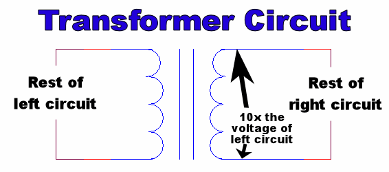
Transformer circuit-symbol

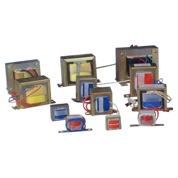
Real-life transformers consist of two wires wrapped around a metal pole
Transformers must follow the rule
Voltageold x Currentold = Voltagenew x Currentnew (Power Conservation)
Thus as Voltagenew goes up (by, say, replacing the 1:10 transformer with a 1:11), Currentnew goes down.
One equation says that current goes up when voltage goes up, the other says that current goes down. Does this mean that the two equations are incompatible and one must be thrown away when working with transformers? No! The reason is that Ohm’s law applies to single circuits, while the other equation applies to how two separate circuits are related by a transformer.
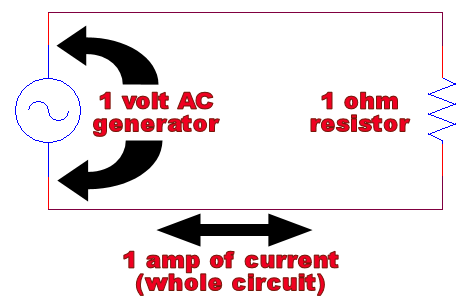
To see this more clearly, imagine the following thought experiment: we connect a 1 volt AC generator to a 1 ohm resistor and measure the current. By Ohm’s Law, we should get 1 ampere of current*:

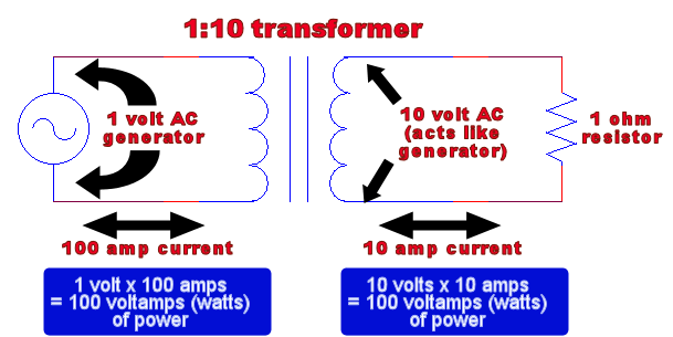
Now imagine we stuck a 1:10 transformer in the circuit, splitting our one circuit into two electrically-separate circuits. The confusion arises from the following question: does the current through the resistor go up because the voltage went up, or down because the transformer needs to conserve power?

Treating the transformer as a 10-volt AC voltage source in the right circuit, we use Ohm’s law to see that the current through the resistor has gone up – it is now 10 amps. In order to preserve power, this means that in the left circuit our original AC power source is now drawing 100 amps of current, 100x what it was drawing before.
This is why high voltage power lines are still dangerous – it’s not that they would cause less current to flow through your body than low-voltage power lines, it’s that the current through your body would be less than the (enormous) current drawn at the lower-voltage end of the power-plant’s transformer.
The most common answer to this question is "No, because transformers are non-ohmic devices." This is baloney – a transformer is nothing more than a pair of inductors, which are perfectly ohmic (ie. they obey Ohm’s law). For our purposes, an inductor can be thought of as a resistor that only resists AC current (this sort of “resistance” is called impedance). This is why the left circuit (above diagram) still obeys Ohm’s law: the transformer acts somewhat like a resistor (due to its impedence) whose resistance goes up as the current demand of the right-circuit goes down.
*As before, when discussing AC voltage/current, when we say 1 volt or amp we really mean 1 rms ("average") volt or amp.
Additional Reading:
- (Un)Common Questions about Electricity
- Why do we use Alternating Current (AC) instead of Direct Current (DC) in power lines?
- What’s the difference between “voltage at a point” and “voltage between two points?” Also, what is ‘ground?’
- Why can the resistor go at the beginning of the circuit OR at the end?
- How is it possible that there’s not a complete circuit to the power plant?


11 Comments
thanks very much for clarifying the doubt…. nice explanation…
This is the only explanation I’ve seen that doesn’t dismiss ohm’s law as ‘not applying here’. Thank you.
To be clear, you are saying that the current does increase in the second circuit, but it increases in the first circuit even more. I just want to be sure on how to reconcile this with the idea that we want transformers to drop current so as to lose less energy on transmission lines. Should I understand that the source is actually a 100 watt source, not 1 watt as shown in your first image, and had we not a transformer, the source would still have put out 100 watts, but with 1 volt, so we would hypothetically have had 100 amps going through the line? So in that sense there is a current drop?
Thanks
Hey Neil – Thanks for the reply!
You seem to be confusing the power (wattage) of a circuit with the power-rating of a power-supply.
The power of a circuit is just V*I (Voltage * Current). This tells you the total amount of power that’s currently being drawn from the power supply. In our first example, there is 1 watt of power being drawn; in the second, there are 100 watts of power being drawn. Both cases, however, use the same 1-volt power supply. The power-supply delivers a fixed voltage, but the current (and therefore the power) drawn also depends on the resistance of the load (aka. everything else in the circuit). This is due to Ohm’s Law.
When we discuss theoretical power-supplies like this, we just assume the power-supply can supply an infinite amount of current if necessary, but in the real world, there is a limit to how much current it can supply. This is given by the it’s power-rating, the maximum power (in watts) the power-supply can output. So when you see, for instance, a 12 volt 180 Watt power-supply, that doesn’t mean it will actually supply 180-watts (ie. 15 amps of current, since 15*12=180) to whatever is plugged into it; it just means it can supply up to 180 watts. How much it actually supplies, again, will depend on the resistance of the load. (So, in that sense, the power supplies in the images above are both infinite-watt)
If you go over the maximum power rating, Bad Things™ will happen – either the power supply will overheat and melt, or explode, or break some other way; or it will lower its voltage and deliver less current than the load requires. Which of these happens depends on what kind of power supply it is (transformer plugged into a wall, physical power generator using magnets, chemical battery cell, etc.) and how it was designed.
Note that when I say “power supply,” I really mean a “voltage source.” There are “current source” power-supplies that deliver a fixed current (and vary the voltage depending on the load), but they are much less common in electronics.
Hope that helps!
sir in the HVDC transmition high voltage is supplied to reduce the power loss in transmittion then here the ohms law is applicable are not so please explain me about the above concept.
Hi. Thank you for the explanation. May I ask a few questions?
1. Does the left circuit of the transformer then obey Ohm’s law? If the left side has a supply voltage of 1Volt, and has 100Amps of current, how does it then obey Ohm’s law if the the current should be V/R?
2. Let’s say the left side power supply has a limit of 100Watts. If we have a 0.5Ohm load on the right side, and the current on the right side = 10V/0.5Ohm = 20A. The power on the right side = 200Watts. Then the left side will try it’s best to draw 200Amps to satisfy the right side? But what happens if it can’t? It can only supply 100Watts… will it blow up? Or what will happen?
Thank you for your explanation once again! 🙂
1. Yes, transformers provide “resistance” in the form of inductance. Without getting too much into it, this is a type of “resistance” caused by the magnetic force in the coils, which only resists AC, not DC. The “total resistance”, combining the actual resistance with the inductance, is called the impedance of the circuit.
Notice that the wiki page for Ohm’s law derives the AC-equivalent of the law, V=IZ (where Z is the impedance)
2. Yes, if you exceed the designated wattage of a transformer (or any electrical component), there is a real risk of causing it to break and/or start a fire.
Thank you!
But since the right side power varies with the right side resistance, does that mean that the left side’s impedance somewhat gets affected by what load we put on the right side? Since impedance is sqrt(R^2+(wL)^2), if the right side power is high, does the impedance have to lower itself to allow for higher current and therefore a higher power on the left side to satisfy the conservation of power? and if so, how does the inductance change? (is there something about mutual inductance i have to read about? i am still not sure abt mutual inductance)
Thank you so much for your reply!
Yes, the impedance of the left side changes depending on the impedance of the right side, in order to satisfy both Ohm’s law and the transformer power equation.
Note that the right-half is a purely resistive load, and the left-side is purely inductive, so it’s equally correct to say “the inductance of the left side changes depending on the resistance of the right”
Thank you! I understand now! 🙂
Wow!! Probably, this question has remained in my mind for 1 year, no satisfactory answer, thnx for such a descriptive answer, i found this link in your comment on: https://physics.stackexchange.com/questions/16459/voltage-and-current-in-transformers/245221 thank you so much 🙂
sir let it be the correct answer but let what about the power and ohms law power say P=VI but which say that V is inversely propotional to I so let it should be explained
Trackbacks/Pingbacks